Why add a heated bed ?
Why add a heated bed ?
 After I made mine, I never had an object pop off by itself because of cooling retraction. Way less issues also when a small plastic blob gets hit by the head while it prints the next layer (which occurs almost all the time with tall and thin structures).
Now there is an update: in this post I explain about how I print reliably, and it works probably even with Nylon and a cold bed!
For the heated bed, I used a single power supply setup, that I attached on the underside of the printer. I now have only the mains and USB cable getting out of the printer, and I carry no more bulky external power supply (that I sometimes forgot to bring with me!). It also reduces the failures due to the tired stock power plug when someone bends over the printer...
This post is divided into 4 parts (...):
- Trying different material for a cold bed (aka no hot bed!)
- Using resistors and a sheet of stainless steel sheet (for reference)
- Using Peltier modules (for reference)
- Working hot bed with a PCB (win)
Trying different material for a cold bed
First, I started printing PLA on the acrylic bed covered by the regular 3M blue scotch. Not so good, as anyone knows, it does not stick that much (or the opposite sometimes!), and the bed needs to be redone all the time with small gaps between the bands.
I also tried the 3M scotch 2090 (aka painters tape, 48mm), which did a bit better.
I did not try to print directly on the naked acrylic bed as some people did, because I really think it would damage it when the head stays low for a while (which happens to me regularly, eg on lost connection or interrupted prints).
 |
| Heat-resistant Kapton tape |
Kapton (picture on the left) was an intermediate and classic choice. Just buy some anyway since it is very useful all the time. It is a kind of heat-resistant scotch that does not degrade with time.
Update: so called "ABS juice" or so is not for me. Anyhow I never use ABS because it does not suit my needs and it stinks (when needed, I use Nylon trimmer line instead). Nylon made me discover a kind of glue which is really nice and which works also with other plastics, so it could be enough when you don't have a heated bed (full details in this post).
I finally decided I really had to get a heated bed (or hot bed, or heating bed, whatever, something semi-hot I would print upon...). What is surprising to me is that Ultimaker still did not provide nor even recommend an "official" one (update: now is a standard with the UM2). And not surprisingly, there are as many heated bed designs as hobbyists.
May be when the market is ready we get heated bed stock with the printer, but for now no design rule them all.
Since I also bought me a printer to hack it, I chose the obvious solution : build one on my own too (YAHB, yet another heated bed).
First attempt: make a hotbed with resistors and a sheet of stainless steel
The kit came with these block resistors (embedded in metallic cases that can be screwed on a support). Actually, they were quite bulky and they were chosen for the R2C2 24V power supply. Powering them with a 19V made them heat slower.
I used a convenient DS18B20 cheap digital sensor to get the temperature and basic relay, which were controlled by a small and cheap arduino pro mini. I also used an optocoupler to separate the signals.

But the final issue was that I just had no aluminum plate at the time. Instead, I used a very stiff 3 mm stainless steel plate (so hard to cut, wow!). But stainless steel is a bad choice when it comes to heating. It was very slow to conduct heat, and failed quite miserably in the end.
The conclusion is : do not even waste spare stainless steel for a bed !
Second attempt: make a hotbed with Peltier modules and plywood support
I had a thin sheet of 1mm aluminum around, no more. It was too thin to try with the resistors, without bending it awfully, so I switched to another design.
I glued the aluminum it to a thick plywood plank for rigidity, in which I had cut two 4cm x 4cm holes, respectively for two TEC12710 Peltier modules I bought on ebay (at around $13). Before using Peltier modules, I recommend reading about them, such as from this FAQ.
Respective heatsinks were held in place with a springy but hard metallic wire (a motorbike wheel spoke, excellent stuff to keep), itself maintained by screws in the plywood (see below). I also added some thermal paste between the Peltier and the aluminum sheet.

Now, this design was simple and clean, for sure. And it was much thinner than with the bulky resistor-based one. I knew the Peltier would not heat much over ~50°, but that may still have been OK for PLA. Hence I did not use any temperature sensor, which is wrong...
Yes it heated... but only for two minutes before it killed itself.
Actually I quickly blew the two Peltier modules. For one, I would better use a fan-based active cooling. But more, I think the power supply I bought was so harsh that the Peltier had time to melt they own core before spreading the heat to the bed (aka reach the reflow temperature). There was no limiting temperature sensor I could check to make them heat progressively : I should have hashed the current flow, and not applied it all, and give more time to reach the target temperature.
The conclusion is : do not use Peltier module to heat your bed like this, unless you want to spend a lot on big ones plus proper cooling ! Even with controlled heating to their maximum, I am not sure they would work in the long term. They would not let you heat enough for ABS plastic neither, so it is a no go in my opinion.
Since I did not want to burn more Peltier modules, which proved to be not so cheap when you destroy them like this, I finally switched to a classic PCB heating element.
BTW, I still like the magic of Peltier modules, and I probably will get back to them one day, but may be for an actively cooled thermal valve. I suspect they are better used for cooling than for heating.
Third attempt: make a working hot bed with a PCB (win)
This one is working really well, and I like the way I did it for the leveling.
Using a PCB as a heater

This is a regular Thing-O-Matic Heater Board v1.1, that I paid $20+$6 on ebay.
It is much smaller than the Ultimaker bed size, but thanks to the aluminum sheet, I do not think it makes a difference in the end. May be it heats less quickly but I get to 55° in one or two minutes, which is OK for me.
By the way, I could have tried first to use thin strips of food aluminum sheets instead, or even some nichrome wire just to try to reduce the BOM. But I wanted a working hot bed now!
 |
| Ouch, what a messy piece of work (but it will be hidden) |
The sensor is a 1 wire dallas DS18B20 (or DS1820). It gives direct digital values so it's extremely easy to interface. It can read up to 125°C which is largely enought for ABS or polycarbonate when you really need high bed temperatures.
I also had to cut one track if I remember near the yellow short cable above. You may find it out by clicking on the picture.
The cables that go to the left are for a LED. However I forgot to drill the aluminum for the LED to be seen from the top on the bed, so I only can see it from the bed side... This is not a big problem since I hear the relay clicking and feel the warm with my hand. Still, it would have been cool to get some light through the bed.

I tried to think of a better way to fix the PCB, but it works quite well like this with Kapton tape... KISS
I paid $8.29 en ebay for a "50mm 5cm X 33m 100ft Kapton Tape High Temperature Heat Resistant". By the way, this Kapton tape is really useful even on cold beds and for protecting the head. Larger tape could be nice, but I find it already difficult to lay this one properly with no spurious folds, so I am not sure a bigger tape would be easier.
Using an aluminum plate to distribute heat and have a flat bed

I drilled with 3mm, and used a 8mm drill (see also this useful tool) for the bevels so the screw heads are flush. I wanted to add a glass on top of the alu bed from the beginning, to protect both the aluminum and the head.
Talking about the aluminum, this is a 3mm thick 25x25 cm item I got for £5+£8 for this "Aluminium Sheet - 3mm x 250mm x 250mm" on ebay. I just could not find the same thickness at local hardware shop, weird. And I suggest this is right, but the minimum thickness for an alu bed whatever you put on top of it.
Using rubber pivot beneath the aluminum bed
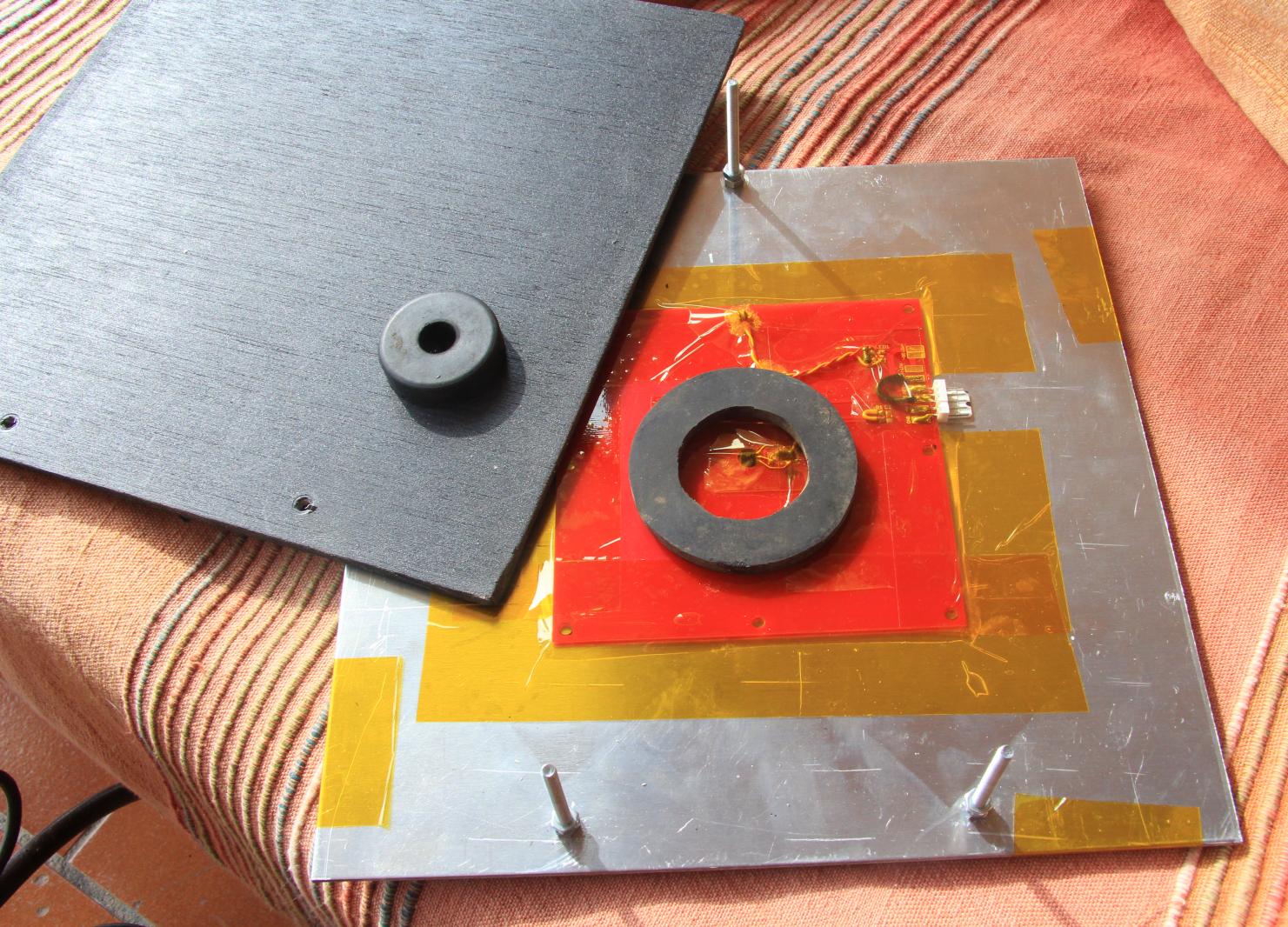
I think this is my real contribution to heated beds : these pieces of rubber really simplify the bed leveling b/c they provide a unique and quite convenient central pivot, with the addition that the 3 screws no more need springs ! One very nice kind of rubber are the halves of destroyed squash balls ; these are almost indestructible (at least without a racket)...
The big ring is to distribute the load on a bigger surface and push firmly the PCB against the aluminum, while leaving some room around the temperature sensor. Its thickness is a bit bigger than that of the 2 nuts on the screws as seen below.
I kept the outside edges open so that heat flows outwards. The aluminum may be heated more uniformly this way (which is probably not significant), but more importantly, it cools down faster after a print by letting hot air flow outside.
 |
| The layered bed as seen from the side. I have just enough room to plug the power and signal cables. I added a cheap black plywood bottom layer to avoid wasting heat, and to spread it evenly. |
I painted the wood black with some metallic spray, partly because I did not want to spend the time varnishing it as the rest of the printer ;)
Heated bed final setup
 |
| Final setup: screws should be shortened to get more Z volume (which I never missed so far) |
Once again, no spring and only three screws made me quite happy compared to the initial setup !
The real trick is the two pieces of rubber in the middle, that act both as a pivot and a spring.
Also, there are only 3 screws, not 4 of them. They are 3mm thread diameter, I drilled one hole on the back of the Z-carriage. The front one are in the small and already damaged Delrin stock parts.
Next step would be to get rid of the whole existing Z plywood. I have a bit of up/down freeplay because the two Z linear bearing are not clamped enough by the arm plywood, and same with the Z ballscrew (well it's no ballscrew in fact).
Soon or later, I will head towards a triangular support made of steel rods, pointed towards me. And may be add a third vertical rod and linear bearing in the front of the bed to make the whole platform very steady.
Add an overall oven glass on top of the aluminum ?
Finally, I added an oven glass on the top of the aluminum sheet. It was cut for me for a so-called discount price because of its size for about 25€ (huh).
 I really think it improves the setup for two reasons at least :
- it makes the surface absolutely flat (the aluminum is almost never really flat and moves with temperature)
Printing on oven glass or not?
Initially, I was expecting to swap between two glass plates in case the parts were hard to remove, but this proved false even when the bed was kept hot (ie. it's easy to pop the object from the glass, even when hot).
I added Kapton on the glass, not sure why but I like it. May be I feel that it protects the class against scratches, even though an oven glass is almost indestructible (I dropped it once from about 1m20 on the hard floor with barely a scratch!). I think Kapton also gives a tiny bit of margin to better adjust the Z bed leveling, especially as you'll see the head scratch the Kapton when it's too low...
Finally, it improved how the object sticks to the bed.
Since the oven glass extremely robust compared to regular glass that I would not want to use, I even used paper clips to hold it in place with pieces of Kapton under the clip jaws. Using four of them forces contact with the aluminum everywhere. This is NOT recommended for regular glass that probably would break (the two material expand quite differently with heat). In any case, I used two pair of pliers to make the paper clip a bit looser/wider.
In the first picture in this post you'll notice that I added a dumb plastic clamp to keep the cable close to the printer wall, though I could print a smaller dedicated clip.
One single power supply located under the printer

The single-power supply setup (with the extended feet I had to design)
I bought this power supply from ebay (a 300W 24V 12.5A Switching Power Supply, for $26+28), and then I cowardly tuned it to 19V, as there is a convenient trimpot, and so I could solder wires directly to the power connector of the main board. I was glad to get rid of the old and bulky external power supply, and have everything within the printer.
The power supply never had an issue since October 2011.
A second output of the power supply powers an arduino pro mini (see the bottom-left case?). It controls the heated bed temperature through a relay. For now it just does bang-bang with a 1° hysteresis, targeting a fixed temperature of 55°.
Update: I eventually added a small oled screen to the Arduino mini, with a rotary encoder knob to set the temperature (and other settings). Strangely the DS18 goes as far as 100°C without trouble, far beyond its official limit! So I can print trickier materials with it :)
There is a dumb off/on switch that goes to the other side but I plan to add some better interface later (eg. 7-digit led temp display + control), or get back to a thermistor and plug the logics to the main printer board so I benefit from Marlin firmware support.
Integrate the hot bed electronics to the Ultimaker firmware ?
Sincerely, I would not have my hot bed powered by the stock Arduino main board neither the stock power supply. At least buy a bigger power supply, then use a cheap relay (or a huge and costly low-resistance mosfet). And recompile the firmware in order to disable bed PWM (not suited for a relay).
I would not power the Ultimaker with anything else than 19V also because I don't want to take any risks, even though some people used 21V (the regulator is said to get really hot).
Having separate hotbed electronics and control NEVER was an issue to me. May be one day I will switch to a firmware-controller hot bed, but I would have to recompile it because it will not support the convenient DS1820 temperature sensor I used anyway...
Future improvements
There is no main switch at all, but I since added a self shutdown circuit (aka suicide), that also switches the hotbed off. May be I will try a safer watchdog with the pro mini to spy on the printer noise or vibration and shut it automatically when idle for some time.
My setup also powers 2 serial short strips of leds (2x12V). I sticked them on the vertical walls of the box, and though it makes it like the NASA by night, it is not really the most efficient place. I need to design a printed support and post about it.
And finally I highly recommend the liquid glue trick, as it proved to be the most reliable way to print Nylon, even on glass, and it may work even on cold beds.
The electronics and arduino code that drives the relay
The schematics are straightforward: the DS signal goes to pin 12 (see arduino playground for more on this), a switch is added to pin 11 (to the ground to disable heating the bed), and the relay is driven with a small transistor on pin 10 to avoid asking too much current from the arduino pro mini (why? how? see this detailed post for example). I even could use a single AVR 8 pin chip, not an $10 arduino.As shown here, the temperature is hard-coded to 55°, here is the raw source code:
#define DS18S20_ID 0x10
#define DS18B20_ID 0x28

#define PIN_BED_SWITCH 11 // on/off main switch to enable/disable heating the bed
#define PIN_RELAY 10 // the relay pin

#define BED_TEMP_MIN 54
#define BED_TEMP_MAX 55
//
// OneWire Library:  http://www.pjrc.com/teensy/td_libs_OneWire.html
//

#include <OneWire.h>
OneWire ds(12); // the DS18 sensor pin
byte dsAddr[8];

long prevMillis= 0;
enum { TMP_OK=0, TMP_AVAILABLE=0, TMP_IN_PROGRESS=1, TMP_NOT_FOUND=-1, TMP_BAD_CHECKSUM=-2, TMP_UNKNOWN_DEVICE=-3 };
int getTemperature(byte addr[8], float* temp)
{
  *temp= -100;
  if(addr[0]==0) return TMP_NOT_FOUND;
  byte i;
  byte present = 0;
  byte data[12];

  if(prevMillis==0) // start conversion
  {
    ds.reset();
    ds.select(addr);
    // Start conversion
    ds.write(0x44, 1); // RequestScratchPad
    // Will wait some time...
    prevMillis= millis();
    return TMP_IN_PROGRESS;
  }

  if(millis() < prevMillis + 850)
    return TMP_IN_PROGRESS;

  // Issue Read scratchpad command
  present = ds.reset();
  ds.select(addr);
  ds.write(0xBE); // ReadScratchPad
  // Receive 9 bytes
  for(i=0; i<9; i++)
    data[i]= ds.read();

  // Calculate temperature value
  *temp= ( (data[1] << 8) + data[0] )*0.0625;
  prevMillis= 0;
  return TMP_AVAILABLE;
}

int initTemperature(byte addr[8])
{
    //find a device
    if(!ds.search(addr))
    {
      Serial.println("No sensor found!");
      ds.reset_search();
      return TMP_NOT_FOUND;
    }
    if(OneWire::crc8( addr, 7) != addr[7])
      return TMP_BAD_CHECKSUM;
    if(addr[0] != DS18S20_ID && addr[0] != DS18B20_ID)
      return TMP_UNKNOWN_DEVICE;
    return TMP_OK;
}

void setup()
{
  Serial.begin(9600);
  ds.reset_search();
  initTemperature(dsAddr);
  Serial.println("INIT OK");
  pinMode(PIN_RELAY, OUTPUT);
  digitalWrite(PIN_RELAY, LOW);
  pinMode(PIN_BED_SWITCH, INPUT);
  digitalWrite(PIN_BED_SWITCH, HIGH); // internal pull-up resistor
}

float lastTemp=0;
void loop()
{
  if(digitalRead(PIN_BED_SWITCH)==LOW)
  {
    digitalWrite(PIN_RELAY, LOW);
    Serial.println("Disabled by switch");
    while(digitalRead(PIN_BED_SWITCH)==LOW)
    {
      digitalWrite(13, HIGH);
      delay(100);
      digitalWrite(13, LOW);
      delay(1900);
    }
    Serial.println("Enabled by switch");
  }

  digitalWrite(13, HIGH);
  delay(200);

  float t;
  int err= getTemperature(dsAddr, &t);
  if(err<0)
  {
    Serial.print("Error #");
    Serial.println(err);
  }
  else if(err==TMP_AVAILABLE)
  {
    Serial.print("Temperature: ");
    Serial.print(t);
    if(t<BED_TEMP_MIN)
    {
      digitalWrite(13, HIGH);
      digitalWrite(PIN_RELAY, HIGH);
      Serial.println(" (heating)");
    }
    else if(t>BED_TEMP_MAX || (t>BED_TEMP_MIN && t-lastTemp>0))
    {
      digitalWrite(13, LOW);
      digitalWrite(PIN_RELAY, LOW);
      Serial.println(" (cooling)");
    }
    else
    {
      Serial.println(" (idle)");
    }
    lastTemp= t;
    delay(650);
  }
}
Feel free to ask for more info, and, yes, you need a heated bed also ; it really changed my life ;)


Thanks for this! Great article, I'm adding a heat bed to my Flash Forge Finder. Didn't even cross my mind to implement a µC.
ReplyDelete